 International
 Singapore
 Malaysia
 Thailand
 Vietnam
Your shopping cart is empty!

IRIV PiControl - Node-RED Modbus-RTU - Power Meter
- Abdulrahman Alhamed
- 20 Mar 2024
- Tutorial
- Advanced
- 440
In this tutorial, we will see how we can monitor the readings of the power meter using Node-RED.
Hardware
- IRIV PiControl
- 24DCV Power Supply
- ADL 200 Power Meter
- 24DCV Relay
- 3-Pin AC Plug
Connection Diagram
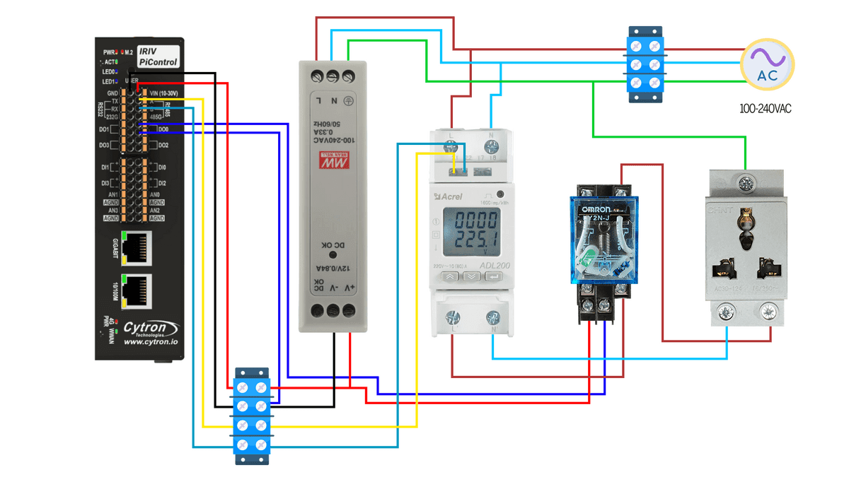
Caution: Please be aware that certain components may operate on AC Power, which can be hazardous if not handled correctly. Ensure that you thoroughly understand the schematic diagram and are capable of performing the electrical wiring accurately. Please turn off any power supply before doing electrical wiring.
Power Supply Connection:
- Start by powering up the power supply using 120-240V AC source.
- Connect the power supply to the IRIV PiControl.
Relay & Power Meter Connection:
- Power up the power meter using the 120-240V AC source.
- Connect the Live (L) and Neutral (N) wires from your AC power supply to the corresponding L and N terminals on the power meter.
Connect the N terminal of the power meter to the N terminal of the load. We are using a 3-Pin AC Socket as our load, allowing us to plug in various appliances to serve as the load.
For the L terminal, it should be connected to one side of the relay, while the other side of the relay connects to the L terminal of the load. This setup ensures proper control and safety between the power meter and the load.
Connect terminal 21 to RS485 A and terminal 22 to RS485 B on the IRIV PiControl (Refer to your Power Meter's manual for pin specifics
Connect one end of the relay to the power supply. Connect the other end of the relay to the DO0 (digital output 0) pin on the IRIV PiControl.
Node-RED Programming
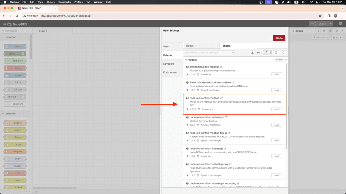
To start on Node-RED, first we need to install Modbus nodes. You can do this using the Node-RED palette manager. Then, Look for these Modbus nodes (node-red-contrib-modbus), and install them.
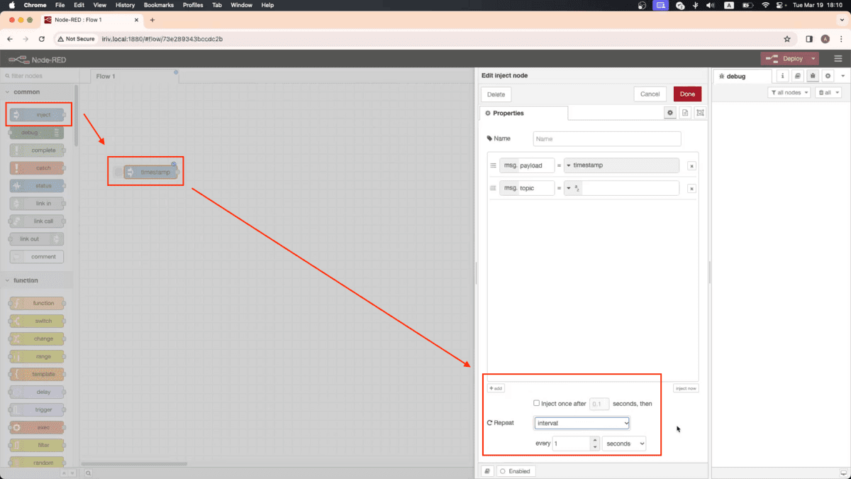
We will start by dragging an inject node onto the flow. Open its properties and set (Repeat) to interval every 1 second.
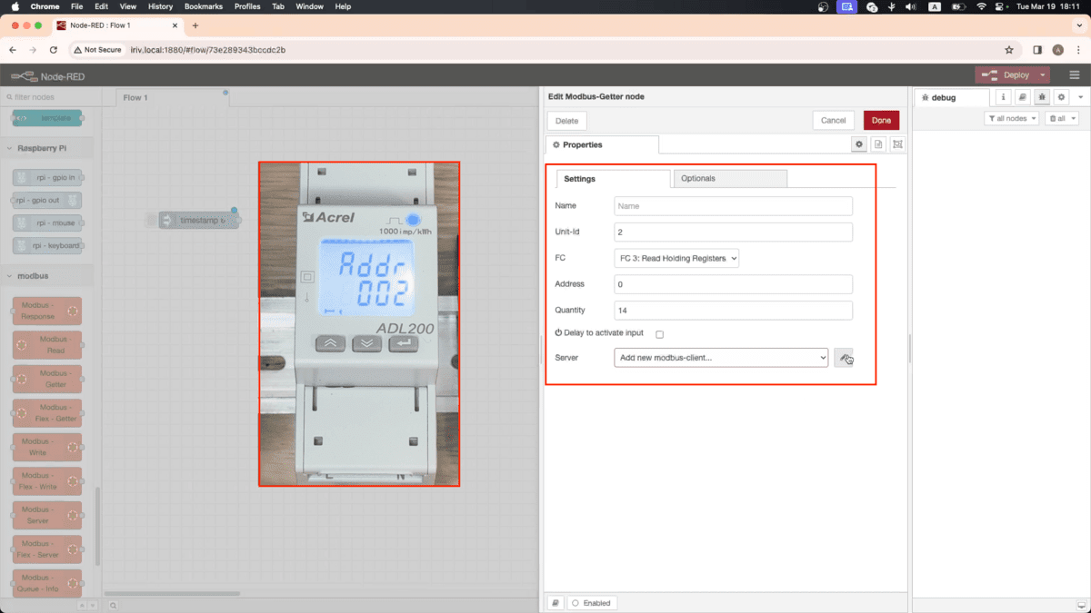
Next, drag and drop (Modbus Getter) node and open its properties window.

Adjust the following settings:
Unit-Id: 2
When communicating with a Modbus device, you need to specify its unit ID so that the data exchange occurs with the correct device. Navigate through your power meter's settings to locate the unit ID. In my setup, the unit ID is 2.
FC: FC 3: Read Holding Registers
This the function code, and it specifies the type of Modbus function to be performed.
Address: 0
The address specifies the starting register from which data will be read or written. Type in 0.
Quantity: 14
The quantity specifies the number of registers to be read or written. Type in 14.
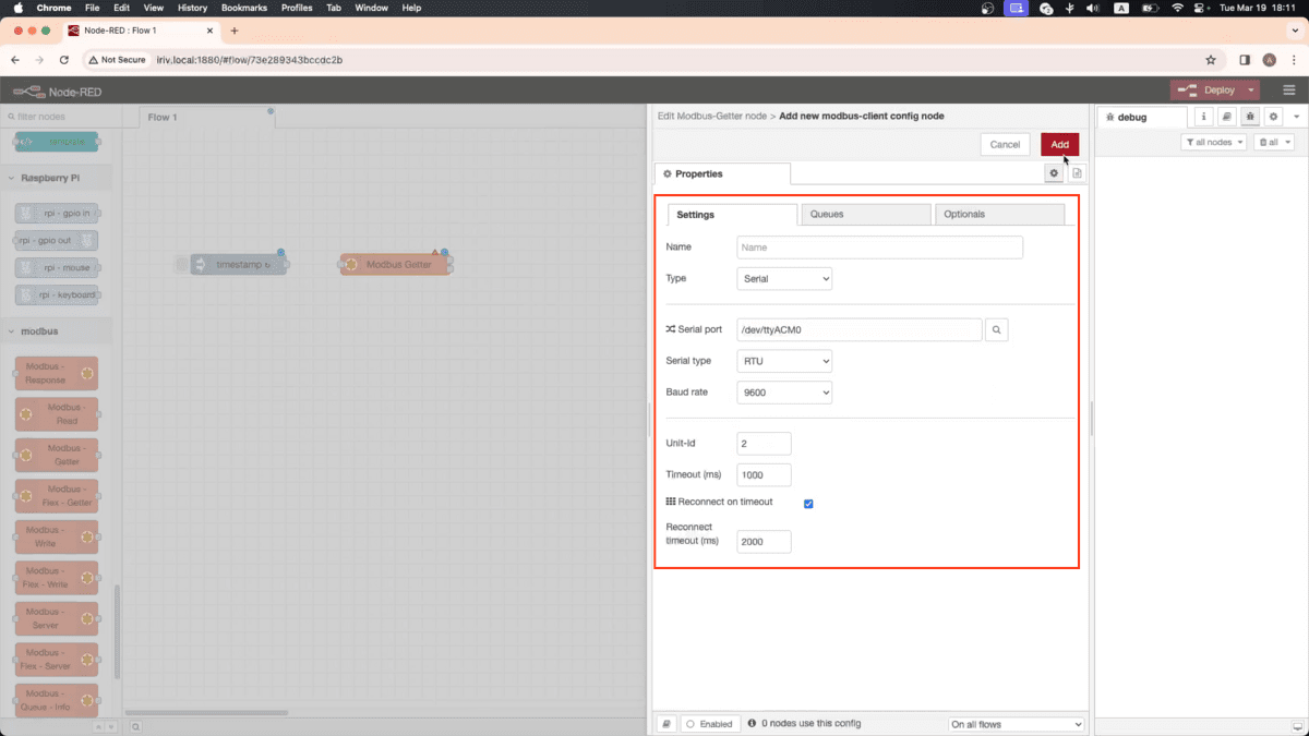
Next, we have to edit the server settings. Change the server Type to Serial. For the serial port, click on the search icon, and then choose this port (/dev/tty/ACM0).
Change the serial type to RTU, and change the unit ID. Click on Add, then close the window.
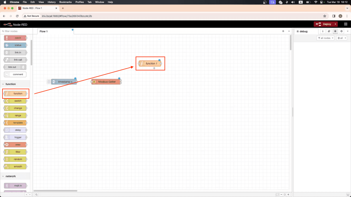
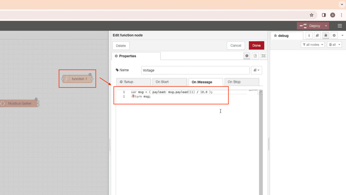
Now, drag a function node to get the Voltage readings, open its properties and write this short code.
var msg = { payload: msg.payload[11] / 10.0 };
return msg;
Number 11 in this line is to get the Voltage reading from the power meter.
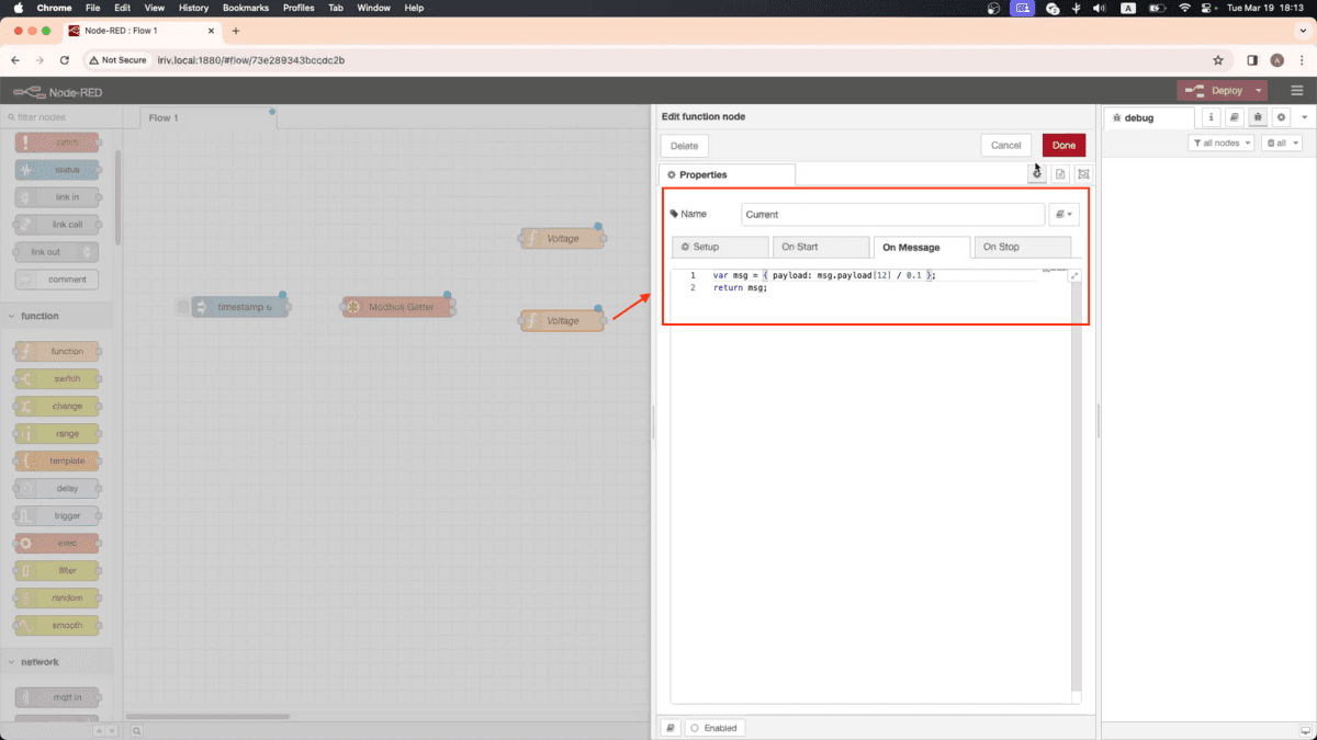
Next, drag another function node to get the Current readings, open its properties, and write this code, make sure to adjust this number to 12, to get the Current readings.
var msg = { payload: msg.payload[12] / 0.1 };
return msg;
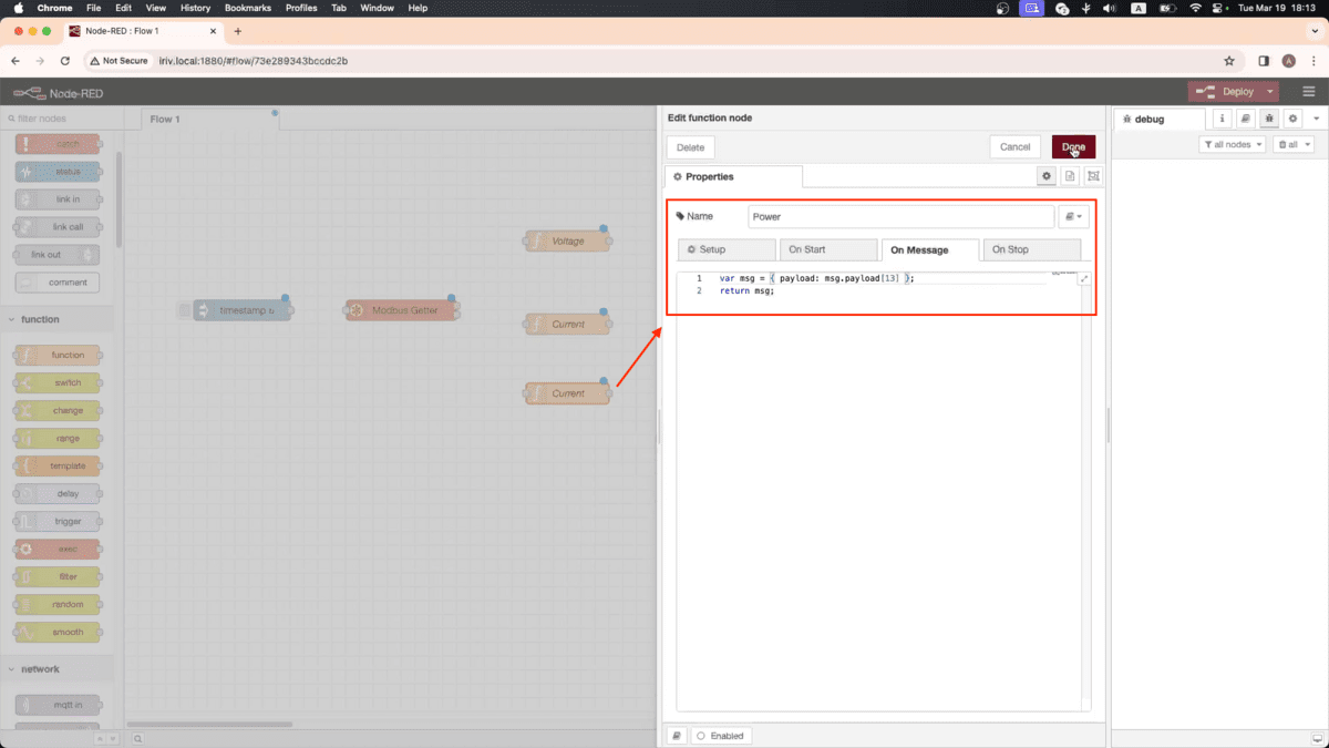
We also need one more function node to get the Power readings, write the same code, and adjust this number to 13.
var msg = { payload: msg.payload[13] };
return msg;
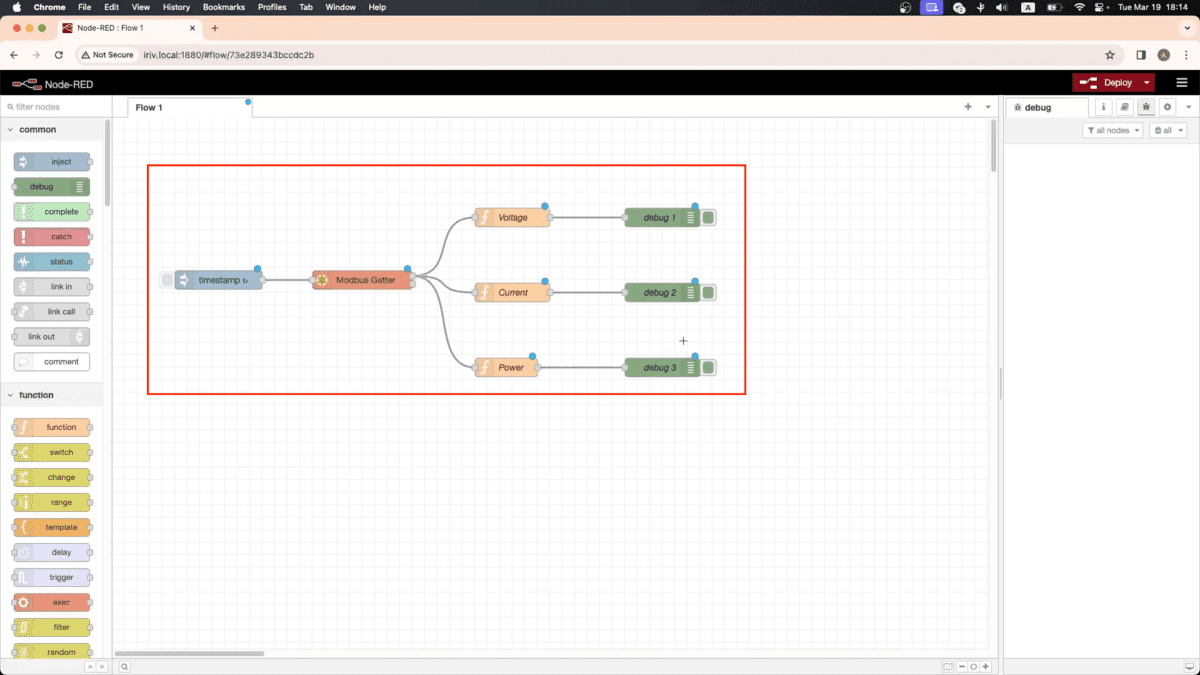
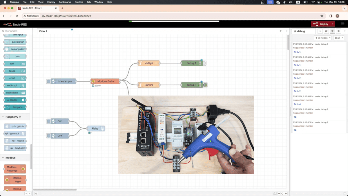
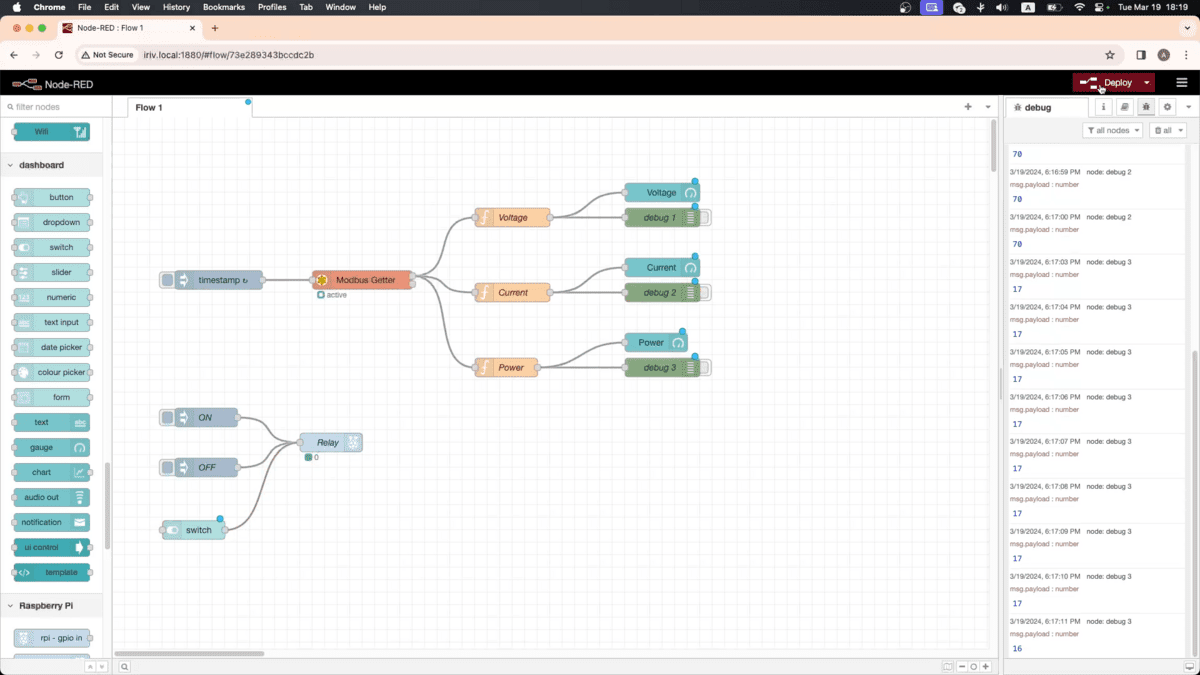
Now, drag 3 debug nodes to display the readings in the debug window. Connect all the nodes together this way.
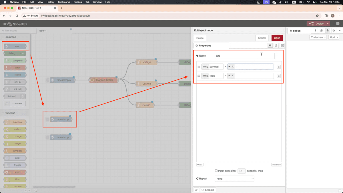
Next drag two inject nodes so we can control the relay through them. Open the first one and write number 1 next to payload, to turn ON the relay.
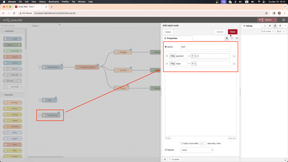
Open the second one and write number 0, to turn OFF the relay.
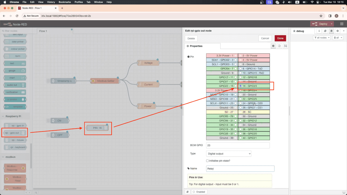
Drag GPIO-out node, and assign it to the relay pin, which is 23. Connect the inject nodes to the relay.
Then click Deploy, Once we activate the relay, you will notice the readings of the power meter appear in the Debug window.
Now, let’s see how we can display the readings in a dashboard.
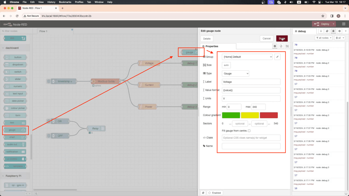
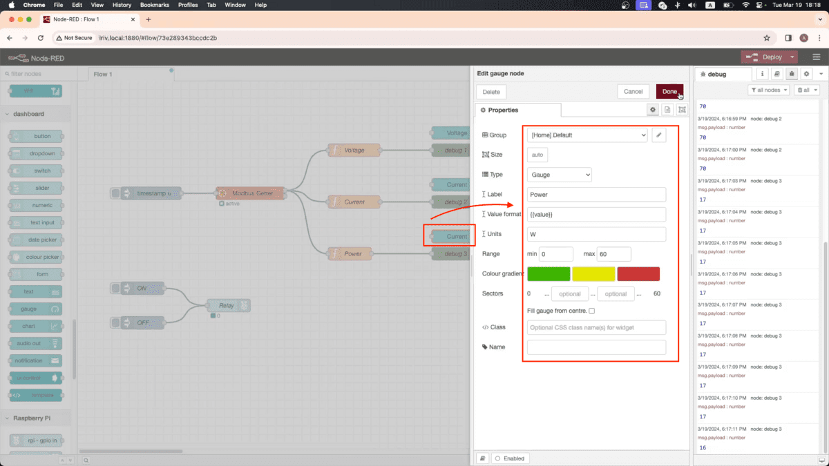
We will need 3 gauge nodes, open the first one, and adjust these settings for Voltage readings.
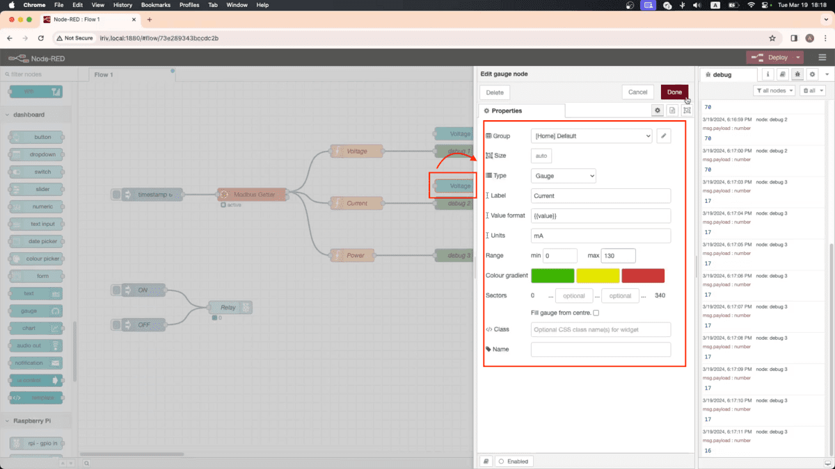
Open the second one, and adjust these settings for Current readings.
Open the third one, and adjust these settings for Power readings.
Lastly, drag a switch node and connect it to the relay. Then, hit Deploy.
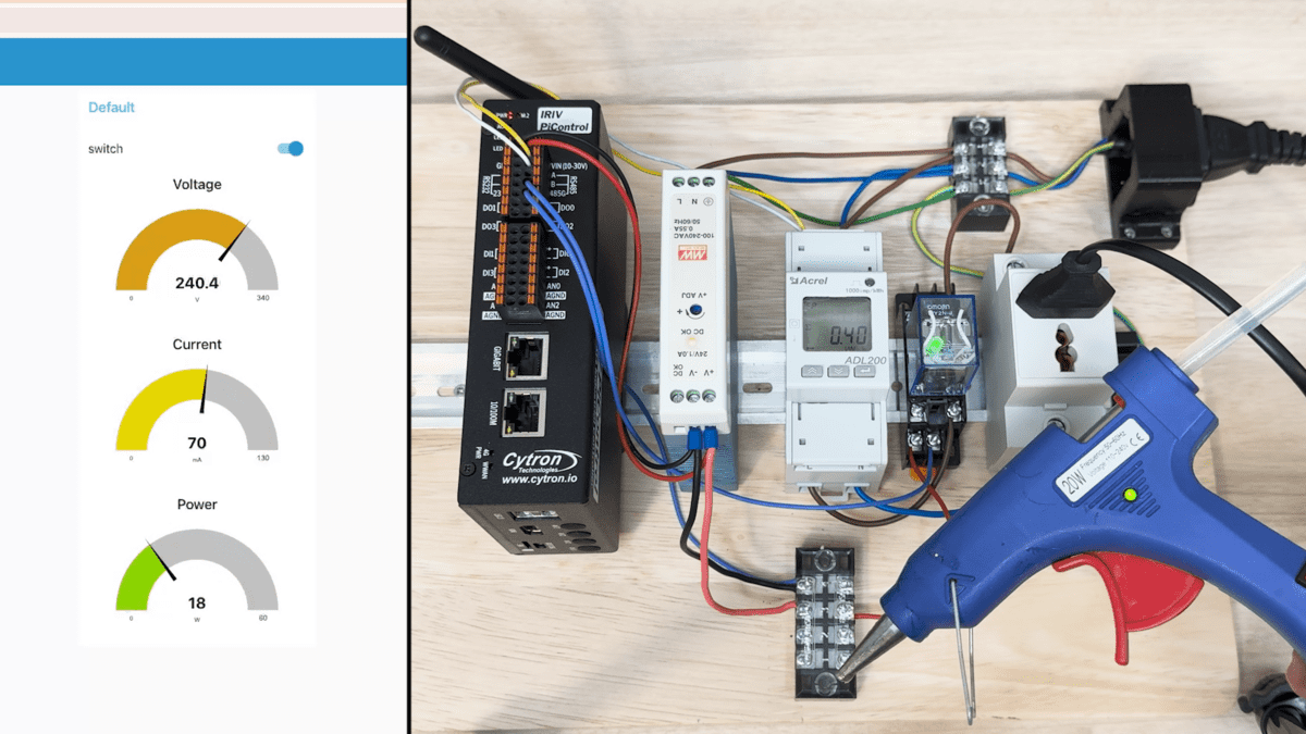
After that, open a new tab in your browser, and type in this address to access the dashboard (iriv.local:1880/ui)
And there you go, now you can control the relay and monitor the power meter readings through this Node-RED dashboard.
That’s all for this tutorial, thanks for reading, and stay tuned for more.
Hardware Components

IRIV PiControl - IR4.0 CM4 Industrial Controller
$279.00++ $279.00
x 1 unit(s)